
In the field of thermal engineering, efficiency is always the central objective. Although cooling towers and pipeline networks are large and highly visible in industrial sites, the key equipment that truly determines heat transfer efficiency is often hidden within much more compact structures. The most typical examples are the plate heat exchanger and its enhanced variant, the spiral heat exchanger. This article provides a detailed analysis of the heat exchangers' structures, working principles, selection guidelines, and maintenance methods.
To understand why plate heat exchangers can achieve such high efficiency, it is necessary to first examine their internal structure and operating mechanism. The following explanation covers five aspects: core structure, fluid dynamics principles, material selection, flow arrangement, and main components.
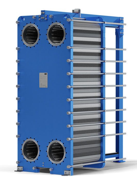
The core structure of a plate heat exchanger can be understood as a “thermal sandwich configuration.” Inside the unit, a series of corrugated metal plates are tightly stacked together. Each metal plate acts as part of the heat transfer interface, with hot fluid flowing on one side and cold fluid flowing on the other.
A key design feature lies in the corrugated surface of the plates. These herringbone-like or wave-shaped patterns serve two main purposes: first, they enhance mechanical strength; second, they induce turbulence in the fluid. The formation of turbulence breaks the laminar flow state and continuously mixes the fluid near the plate surface, significantly improving heat transfer efficiency.
From a fluid dynamics perspective, the corrugated structure acts like a continuous “agitation” mechanism. For example, when a hot liquid cools under static conditions, heat transfer efficiency is limited to surface conduction. However, if internal fluid motion is induced so that hotter fluid continuously reaches the heat exchange surface, overall efficiency increases significantly.
The corrugated plates in a plate heat exchanger achieve exactly this effect. They enhance heat transfer performance by maintaining continuous fluid disturbance, allowing extremely high heat transfer density within a very small volume.
In terms of material selection, stainless steel is typically used as the standard material for plate heat exchangers. Stainless steel offers a good balance of thermal conductivity, corrosion resistance, and cost-effectiveness. However, in highly corrosive environments such as seawater or acidic media, titanium or other special alloys are required to ensure service life.
The heat transfer plates themselves are extremely thin, typically only 0.5 to 0.8 mm thick. This thin-wall structure is not a weakness; rather, it is a key factor in achieving high efficiency. The lower the thermal resistance, the faster the heat transfer rate.
Plate heat exchangers mainly use a counterflow configuration. Counterflow means that hot and cold fluids move in opposite directions. This maintains a relatively constant temperature difference throughout the heat exchange process, maximizing the driving force for heat transfer.
In contrast, parallel flow causes the temperature difference to drop rapidly, reducing efficiency. In counterflow systems, the terminal temperature difference can approach 1°C, whereas traditional shell-and-tube heat exchangers typically achieve only 5–10°C. This difference highlights the superior energy efficiency of plate heat exchangers.
The working principle of a plate heat exchanger is based on alternating plate channels that guide hot and cold fluids separately. Heat exchange occurs through the metal wall due to temperature differences, while turbulence inside the channels significantly enhances heat transfer efficiency.
The core structure consists of the following components:
The heat transfer plates are the most critical elements. They are usually made of thin stainless steel sheets such as 316L, formed by stamping into herringbone corrugations. These corrugations not only increase structural strength but also promote turbulence, improving the heat transfer coefficient. Geometric parameters such as corrugation angle, channel spacing, distribution zone design, and stamping depth are optimized according to fluid viscosity, fouling risk, and pressure drop requirements to balance efficiency and flow resistance.
The gaskets are typically made of elastomer materials. Their main functions are sealing the plate edges and media channels to prevent leakage and guiding fluids into the correct alternating flow paths. Common sanitary gasket materials include NBR and EPDM. NBR is suitable for oil-based media, while EPDM is more suitable for hot water and steam applications.
The frame consists of a fixed head and a movable pressure plate. It holds the entire plate pack in place and uses upper and lower guide bars for alignment. The frame bears all mechanical loads, provides flange connections, controls compression force, and allows opening for maintenance, cleaning, and inspection.
Tension bolts are used to compress the plate pack to the designed thickness. Tightening in a diagonal sequence ensures uniform stress distribution, preventing deformation, maintaining gasket sealing performance, and ensuring structural alignment during operation.
When handling fluids containing solid particles or high viscosity, conventional plate heat exchangers are prone to clogging. For such complex conditions, spiral heat exchangers were developed, offering distinct performance advantages due to their unique structure.
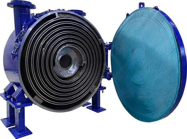
A spiral heat exchanger is designed for highly polluted or viscous media. It consists of two continuous metal strips wound into spiral channels, allowing hot and cold fluids to flow through two separate continuous spiral paths. This structure resembles a “metal-rolled spiral channel,” effectively preventing multi-channel blockage.
Unlike traditional multi-channel plate heat exchangers, the spiral structure has a single continuous flow path. Therefore, even if local deposition occurs, it does not lead to complete system failure.
One of the most significant advantages of spiral heat exchangers is their self-cleaning capability. When deposits form in the fluid, the single-channel nature causes local blockage to increase local pressure, which in turn increases flow velocity and flushes away the deposits automatically.
In addition, the spiral flow structure generates centrifugal effects, keeping solid particles suspended and preventing sedimentation on the wall surface. The flow also produces Dean vortices—transverse rotational flows that continuously scour the surface, further reducing fouling risk.
The structure of a spiral heat exchanger consists of three main parts: spiral coil, flow channels, and outer shell.
The spiral coil is typically made of corrosion-resistant materials such as stainless steel. It guides hot and cold fluids through a continuous spiral path, significantly increasing residence time and heat transfer contact area.
The flow channels are formed by the gaps between adjacent spiral coils. They guide alternating hot and cold media and can be designed for either counterflow or parallel flow. Counterflow is more commonly used to improve efficiency. Channel geometry directly affects flow behavior and pressure drop.
The outer shell encloses the entire spiral core, providing structural support, sealing, and rigidity. It withstands internal pressure, prevents leakage, and ensures stable operation under high temperature and high pressure conditions.
Spiral heat exchangers offer multiple geometric configurations.
Single-channel designs are typically used for clean fluids with low fouling tendency. In such cases, a single continuous flow path is sufficient to achieve efficient heat transfer.
Multi-channel designs are more suitable for complex media systems. For example, when one side contains high-viscosity or fouling-prone fluids while the other side is relatively clean, multi-channel configurations improve flow distribution, enhance thermal stability, and reduce clogging risk.
Flow direction also significantly affects performance. Axial flow structures are suitable for low-viscosity fluids and moderate heat transfer requirements, offering relatively straight flow paths and low pressure drop. Radial flow structures are more suitable for high-viscosity fluids or compact equipment layouts, as they increase turbulence and improve heat exchange efficiency.
Due to their structural differences, these two types of heat exchangers have developed distinct application advantages. Understanding typical use cases helps engineers make appropriate selections.
Plate heat exchangers are widely used in industrial systems, HVAC applications, and sanitary industries such as food processing, brewing, and biopharmaceutical production due to their compact structure, high performance, and cost-effectiveness. They are particularly suitable for heating, cooling, heat recovery, and pasteurization of clean, low-viscosity fluids.
For example, in dairy processing, pasteurization requires heating milk to high temperatures and then cooling it. Without heat recovery, separate heating and cooling systems would be required continuously. With a plate heat exchanger, the hot product can preheat incoming raw material, enabling internal energy recycling and significantly reducing energy consumption.
Spiral heat exchangers are widely used in wastewater treatment, biological sludge heating, and the paper industry, where fluid conditions are complex.
In wastewater treatment plants, they are used to heat anaerobic digestion tanks or recover sludge heat energy. Since these fluids contain large amounts of suspended solids, traditional heat exchangers are prone to clogging, while spiral designs effectively prevent such issues due to their self-cleaning capability.
In the paper industry, spiral heat exchangers handle highly viscous and particle-laden fluids such as black liquor, which presents significant challenges for conventional equipment.
Selecting the correct heat exchanger type depends on process conditions and fluid characteristics.
For clean, low-viscosity fluids requiring extremely high heat transfer efficiency, plate heat exchangers are the best choice. They provide a very high heat transfer surface area-to-volume ratio within a compact footprint.
For high-viscosity, particle-laden, or fouling-prone media, spiral heat exchangers offer clear advantages. Their single continuous flow path and self-cleaning capability significantly reduce clogging risk and maintenance frequency.
In space-constrained systems requiring high efficiency, plate heat exchangers are more suitable. In applications requiring higher anti-fouling capability or stronger structural robustness, spiral configurations are preferred.
Once in operation, maintenance is essential to ensure long-term stable performance. Fouling is a common challenge for all heat exchangers.
The main operational challenge is deposition and fouling. As operating time increases, flow resistance rises, pressure drop increases, and heat transfer efficiency declines. These are early indicators of internal fouling.
In engineering practice, changes in pressure drop and temperature difference are monitored to determine when cleaning is required. Once performance degrades beyond a threshold, online cleaning or disassembly cleaning is performed.
Cleaning typically involves three steps: acid cleaning to remove inorganic scale, alkaline cleaning to remove organic deposits, and final disinfection. Each step must be carefully controlled in terms of temperature, flow rate, and duration to avoid damaging plates or gasket materials.
Beyond technical performance, economic efficiency is a key factor in investment decisions.
From an economic perspective, these heat exchangers offer very high return on investment. In many industrial systems, heat recovery can reduce energy consumption by more than 30%.
For example, in dairy processing, internal energy recycling using a plate heat exchanger can achieve a payback period of one to two years. This rapid return makes heat exchanger upgrades an effective strategy for energy-saving and cost reduction in industrial enterprises.
Plate heat exchangers and spiral heat exchangers represent advanced developments in modern heat transfer technology in terms of efficiency, compactness, and adaptability. By precisely applying fluid dynamics and heat transfer principles, they enable higher energy efficiency within smaller equipment footprints.
Plate heat exchangers are ideal for clean, low-viscosity fluids requiring high-efficiency heat transfer, while spiral heat exchangers excel in handling highly contaminated or viscous media. Proper selection and maintenance of these two types of equipment can significantly improve energy utilization efficiency and reduce operating costs, making them essential components of modern industrial energy-saving systems.